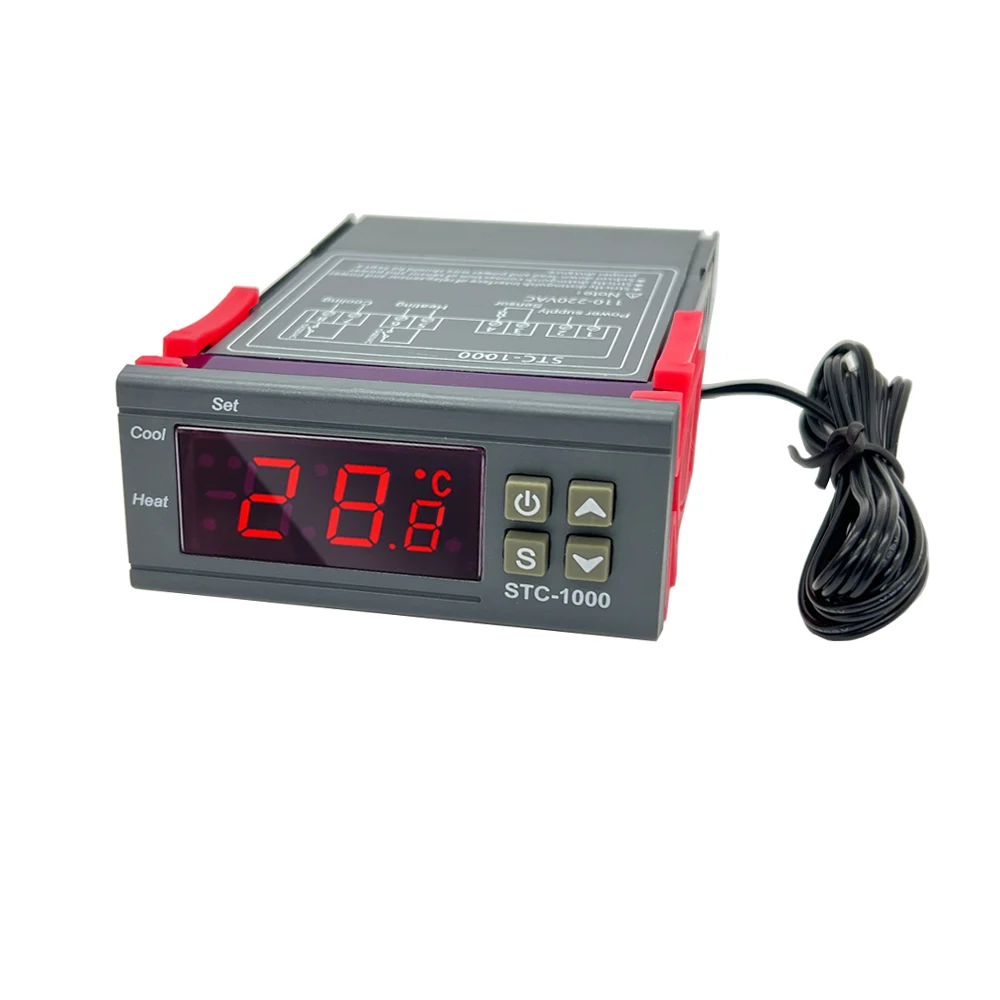
Digital Temperature Controller Thermostat Thermoregulator incubator Relay LED 10A Heating Cooling STC-1000 STC 1000 12V 24V 220V
Digital Temperature Controller Thermostat Thermoregulator incubator Relay LED 10A Heating Cooling STC-1000 STC 1000 12V 24V 220V
Impossible de charger la disponibilité du service de retrait
SPECIFICATIONS
Brand Name: GlintDeer
Cable Length: 1M
Certification: CE
Display Size: 1.9 Inches & Under
Display Type: DIGITAL
Is Smart Device: No
Max Measuring Temperature: 70°C- 99°C
Measure Type: K
Model Number: STC-1000 Celsius Temperature controller
Note: send according to order options
Origin: Mainland China
Power Type: Charger
Screw: M6*1
Sensor type: NTC 10K waterproof sensor
Style: Embedded
Theory: Temperature Controller
Type: K
Usage: Household


Switch the modes between cool and heat; Control temperature by setting the temperature setting value and the difference value; Temperature calibration; Refrigerating control output delay protection; Alarm when temperature exceeds temperature limit or when sensor error.
STC-1000 Operation Instruction
Main function
Switch the modes between cool and heat Control temperature by setting the temperature set value and the difference value:Temperature calibration; Refrigerating control output delay protection; Alarm when temperature exceeds temperature limit orwhen sensor error.
Specification and size
◆Frontpanel size:75(L)x34.5(W)(mm) ◆Mounting size:71(L)x29(W)(mm)
◆Product size:75(L)x34.5(W)x85(D)(mm) ◆Sensor length: 1m(include the probe)
Technical parameters
◆Temperature measuring range:-50~99C◆Resolution:0.1C
◆Accuracy:±1C(_50C~70C)
◆Power supply:12V 24V110-220VAC 50Hz/60Hz◆Power consumption:<3W
◆Sensor.NTC sensor(1PC)
◆Relay contact capacity:Cool(10A/220VAC);Heat(10A/220VAC)
◆Ambient temperature: 0C~60C ◆Storage temperature:-30C~75
◆Relative humidity: 20~85%(No condensate)
Panel instruction

Display instruction: Three_digit LED +Minus digit + Status indicator light(Status indicator light (Cool, Heat) + Set indicator light (Set)
Key instruction: " S" key: the key to set; "A" key: Up key;
"" key: Down key; "": the key to tum on and of the power
Indicator light status instruction
lndicator light |
Function |
Noto |
Cool indicator light |
On:Refrigeration starts;Of:Refrigeration slops;Flashcompressordelay |
cool.Heat indicatgrlghit cap notbeon.status simuitaneously |
Heat indicator light |
|on: heating starts;Off:heating stops |
|
set indicator lightl |
on:parameter setting status |
Key operation instruction
1.The way to check parameter:
Under normal working status, press "A" key it displays temperature setting value; press `" key it displays thediference value
2.The way to set parameter
Under controller normal working status, press "s " key for 3s or more to enter parameter modifying mode, and the "Set'indicator light on, screen displays the first menu code "F1"
Press *A"key or " key to adjust up and down and display tho menu iem and the code of the menu item.Press "S" key todisplay the parameter value of the current menu. Press both " s" key and hold "A" key or " key simultaneously to chooseand adjust the parameter value of the current menu value promptly. After finishing the setting, press and release the "O" keyinstantly to save the parameter modified value and returm to display the normal temperature value. If no key operation within10 seconds, system won't save modifed parameter, screen back to display normal temperature.
3.Restore system data
When electrified, system will check itself, screen will display *Er" if error exit, please press any key at this time, and it restoresdefault value and enter into normal working mode. it is advised to reset the parameter value under such conditions.
Operation instruction
Under controller normal working status, press and hold "O" key for 3s can turn off the controller, Under controller "offrstatus, press and hold "" key for 1s can turm on the controller.
Under the controller normal working status, screen displays the current measuring temperature value; also the controller canalso switch the working mode between heating and cooling.
Controller starts refrigerating with cool indicator light on when the measuring temperature value z temperature set value .difference value, and the refrigerating relay is connected; If the "Cool" indicator light flashes, it indicates the refrigeratingequipment is under compressor delay protect status; when the measuring temperature values temperature set value, the Coolindicator light on, and refrigerating relay disconnects
System starts heating when the measuring temperature value s the temperature set value-difference value, and the "Heat'"indicator light on, the heat relay connects; When the measuring temperature z temperature set value, the "Heat" indicatorlight is off, and the heat relay disconnects
Menu instruction
Code |
Function |
set range |
Default |
|
F1 |
Temperature set value |
-50.0~99.9c |
10.0℃ |
|
F2 |
Difference set value |
0.3~10.0℃ |
0.5c |
|
F3 |
Compressor delay time |
1~10 minutes |
3 minutes |
|
F4 |
lermperature calbration value |
-10.0℃~10.0c |
oc |
Error description
Alarm when sensor error: Controller activate the sensor error alarm mode when sensor open circuit or short circuit, all therunning status is cosed off with the buzzer alarms, and the nixie tube displays "EE", press any key can cancel alarm sound,system back to display the normal temperature when the error and the fault is cleared.
Alarm when the measuring temperature exceeds temperature measuring range: Controller activates the error alarm functionwhen the measuring temperature exceeds the temperature measuring range, all the running status is closed off with the buzzeralarms, and the nixie tube displays "HHr, Press any key can cancel alarm sound, system back to display the normal
working mode when the temperature restore to normal measuring range
Safety Regulations
★Danger:
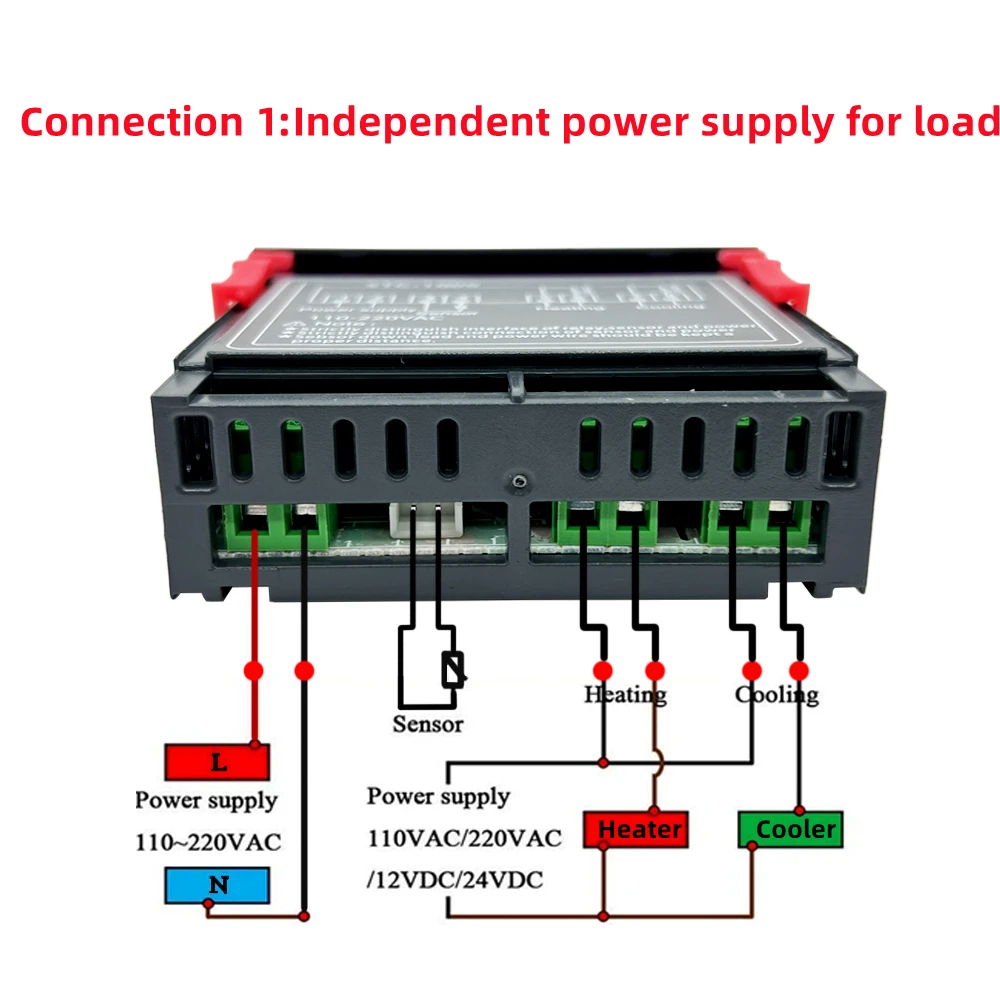
1. Strictly distinguish the sensor down_lead, power wire and output relay interface from one another, and prohibit wrongconnections or overloading the relay
2. Dangers: Prohibit connecting the wire terminals without electricity cut-off.
★Waming:
Prohibit using the machine under the environment of over damp, high temp., strong electromagnetism interference orstrong corrosion
★Notice
1. The power supply should conform to the voltage value indicated in the instruction.
2. To avoid the interference, the sensor down-lead and power wire should be kept a proper distance.
Wiring diagram
lndicator light |
Features |
|
Cool indicator |
On: cooling work;off: cooling off; |
Cool, Heat two instructions can |
Heat indicator |
On: heating work;off:heating off |
|
Set indicator |
On: parameter setting status |